8-bit Computer
Introduction
Computer architecture forms the foundation of any digital system, outlining the organization and interconnection of its various components. In this article, we will explore the fundamental modules that constitute computer architecture, examining their roles and interactions. These modules include the Bus, Registers, Display, Arithmetic Logic Unit (ALU), RAM, Program Counter, Clock, CPU, and additional miscellaneous components.
In this article we will have a look at how it works and also how some of the features of this computer could be used.
The Bus: A Path for Data Exchange
The Bus serves as a set of shared wires enabling the movement of 8-bit data throughout the computer. It allows modules to send data by outputting to the Bus and receive data by accepting inputs from the Bus. LEDs on top of the Bus provide visual representation of the data being transmitted.
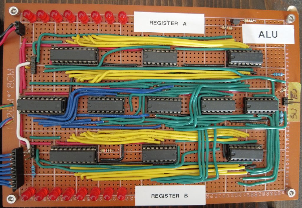
Registers: Temporary Data Storage
Registers are utilized for temporary data storage. The computer architecture described here includes two Registers, each consisting of 8 flip-flops for reading in values from the Bus and an 8-bit buffer for flowing data back out to the Bus. Additionally, LEDs are incorporated to display the contents of the Registers.
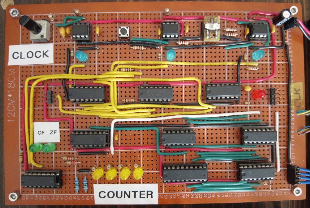
Clock: Regulating Timing
To introduce a sense of time, the Clock module utilizes a 555-timer set to pulse at a consistent rate. The clock’s time constant can be adjusted using a potentiometer, allowing for a range of frequencies. A push-button enables manual advancement of the clock one pulse at a time. The Clock module also incorporates an enable pin to halt the computer when the program execution is complete.
Program Counter: Sequencing Memory Access
The Program Counter is a 4-bit register responsible for tracking the memory address accessed next. At the start of each command step, the RAM utilizes the number stored in the Program Counter to determine the memory address to execute. The counter initializes at 0 and increments by 1 after each step, facilitating sequential memory access. The Program Counter can also read in values, enabling jumps to arbitrary memory locations, thereby enabling looping through specific ranges of memory.
Arithmetic Logic Unit (ALU): Mathematical Operations
The ALU enables mathematical operations on numbers within the computer. In this simplified architecture, the ALU is limited to addition. By utilizing two chained 4-bit adders, the ALU continuously sums the values in the A and B Registers. The current sum of A and B is displayed on LEDs. The ALU also incorporates 8 XOR gates to enable subtraction by inverting the number in the B Register and adding 1. Additionally, a “carry” bit signals when the sum of A and B exceeds 255.
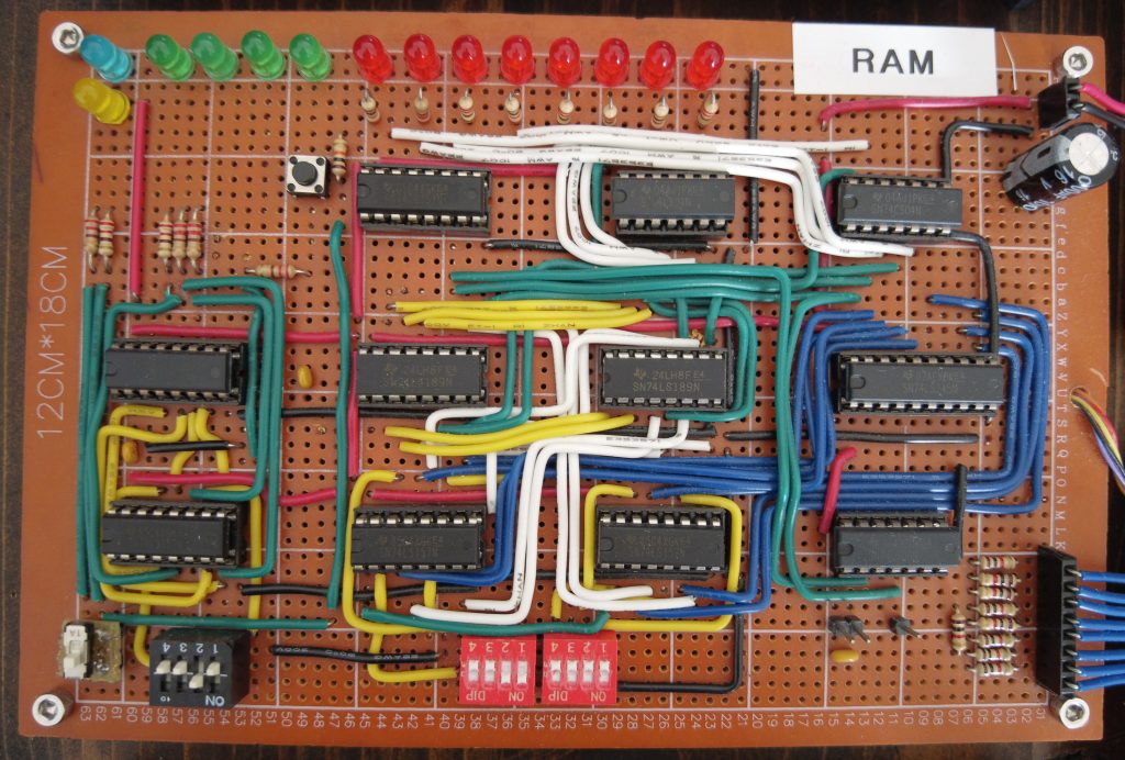
RAM: Memory for Programs and Data
The RAM module provides memory for reading and writing programs and data. It operates with a 4-bit memory address received from the Bus, allowing for 16 lines of memory. Each memory address holds an 8-bit number, which represents either a command ID and an argument or simply an 8-bit number. The RAM incorporates another Register and buffer for outputting data to the Bus, along with LEDs to indicate its operations. The module features two modes: programming mode and run mode. Programming mode allows manual setting of memory addresses and values, while run mode requires the memory address to be provided via the Bus.
Display: Enhanced Data Presentation
To alleviate the burden of reading off numbers from LEDs, a digital Display module is introduced. It functions as another Register capable of loading values from the Bus. The display utilizes 7-segment displays, which require converting binary numbers into a list of segments to be illuminated. This conversion is accomplished using an EEPROM programmed with a lookup table. To create the illusion of a steady display, a small counter, comprised of fast clock and chained flip-flops, rapidly cycles through each of the 4 digits for a given number.
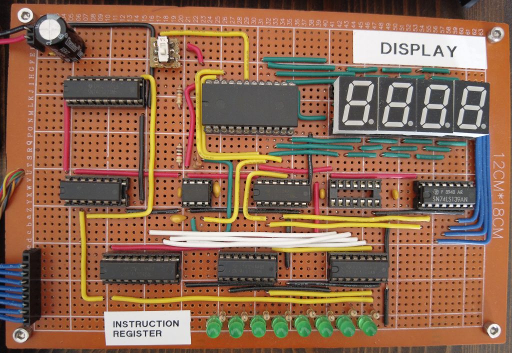
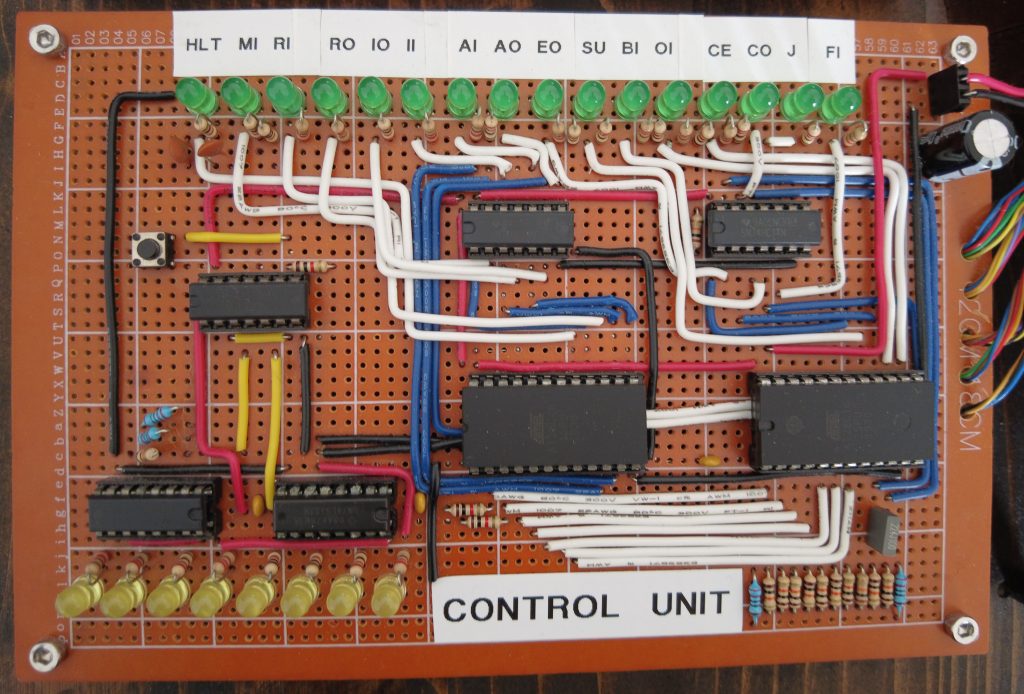
Control Unit
Control unit plays a vital role in coordinating the activities of the various components within the computer. It follows the principles of a finite state machine (FSM) design, which means it operates in a series of defined states and transitions between them based on the current instruction being executed.
To begin, the control unit receives a clock signal, which acts as a timing mechanism. This signal ensures that the computer’s operations are synchronized and occur at the appropriate intervals. The clock signal serves as a heartbeat for the control unit, driving the sequencing of instructions. The instruction to be executed is stored in the Instruction Register (IR). The control unit reads the instruction from the IR and proceeds to decode it.
Decoding involves examining specific bits within the instruction to determine the required operation. For example, certain bits might indicate whether an arithmetic operation, a memory access, or a control flow instruction is needed.
Using EEPROMs, the control unit generates the necessary control signals based on the decoded instruction. These control signals are then sent to the relevant components within the computer. For instance, if an arithmetic operation is required, the control unit will signal the arithmetic logic unit (ALU) to perform the specified operation, such as addition or subtraction.
The control unit also handles the sequencing of instructions. It manages the program counter (PC), which points to the memory location of the next instruction to be executed. After completing the execution of an instruction, the control unit increments the program counter, causing the computer to fetch the next instruction from memory.
By carefully orchestrating the flow of data and instructions, the control unit ensures that the computer operates in a controlled and orderly manner. It provides the necessary coordination and timing for the various components to work together harmoniously, enabling the computer to perform a wide range of computations and tasks.
Leave a Reply